


-
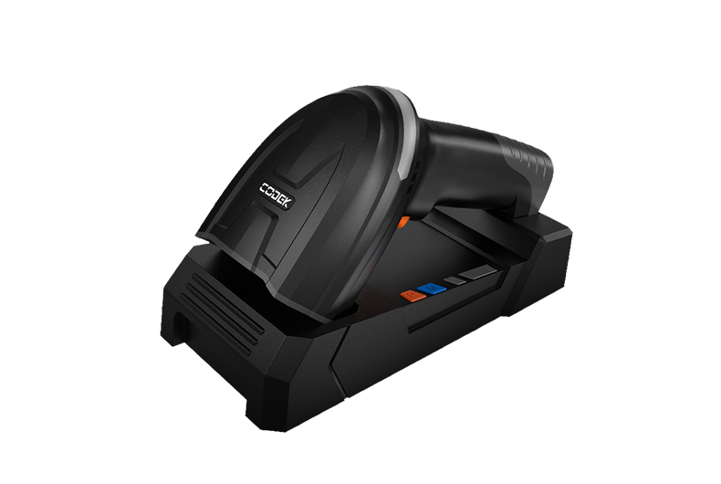
 UROVO's K180 Wireless Barcode Scanner Receives 2026 Red Dot Product Design AwardUROVO, a global leader in industry application solutions, announced that its K180 Wireless Barcode S...2026-05-07
 -
 Stop Losing Revenue Across Your Entire Store: Meet UROVO's2026 Flagship Retail LineupEvery second of store operation either builds revenue or erodes it.The operational reality: • Inac...2026-04-07
 -
 UROVO Recognized as Google’s Android Enterprise Gold PartnerUROVO, a leading provider of intelligent enterprise mobility solutions, has officially achieved Andr...2026-04-03
UROVO Partner program offers you access to our industry-leading products and exclusive resources so you can grow faster and stronger. Submit an application to become a Urovo Partner today!


- Home
-
Products
-
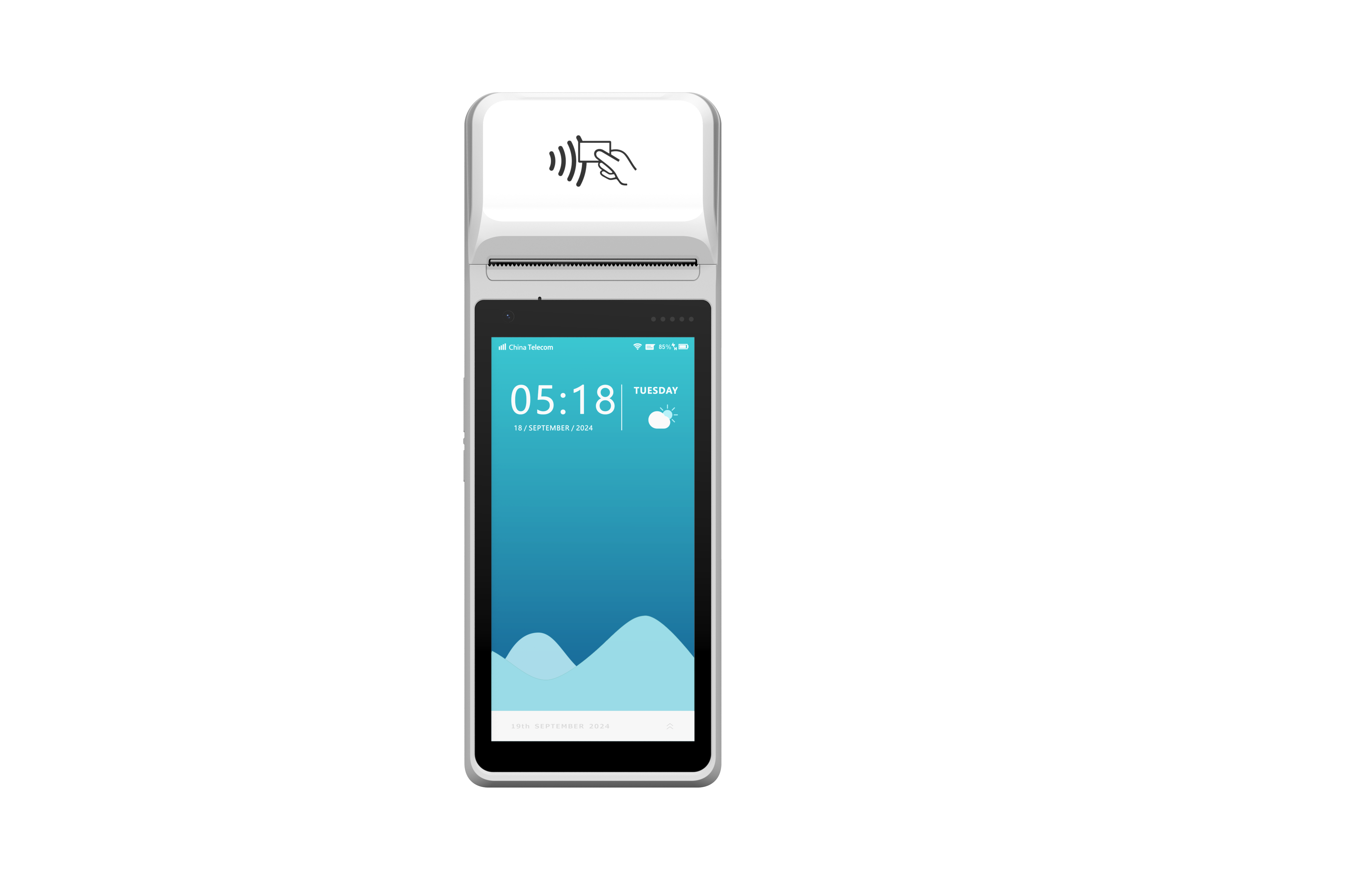
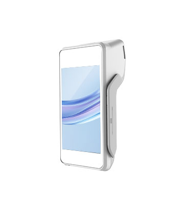
Payment Terminals
 i9200
New
i9200
New
 i9200(Non-financial)
New
i9200(Non-financial)
New
 i5300L
New
i5300L
New
 i5300
New
i5300
New
 i9100
i9100
 i9000S
 i5000
i5000
 Q200
Q200
-
Mobile Computers
Handheld Mobile Computer
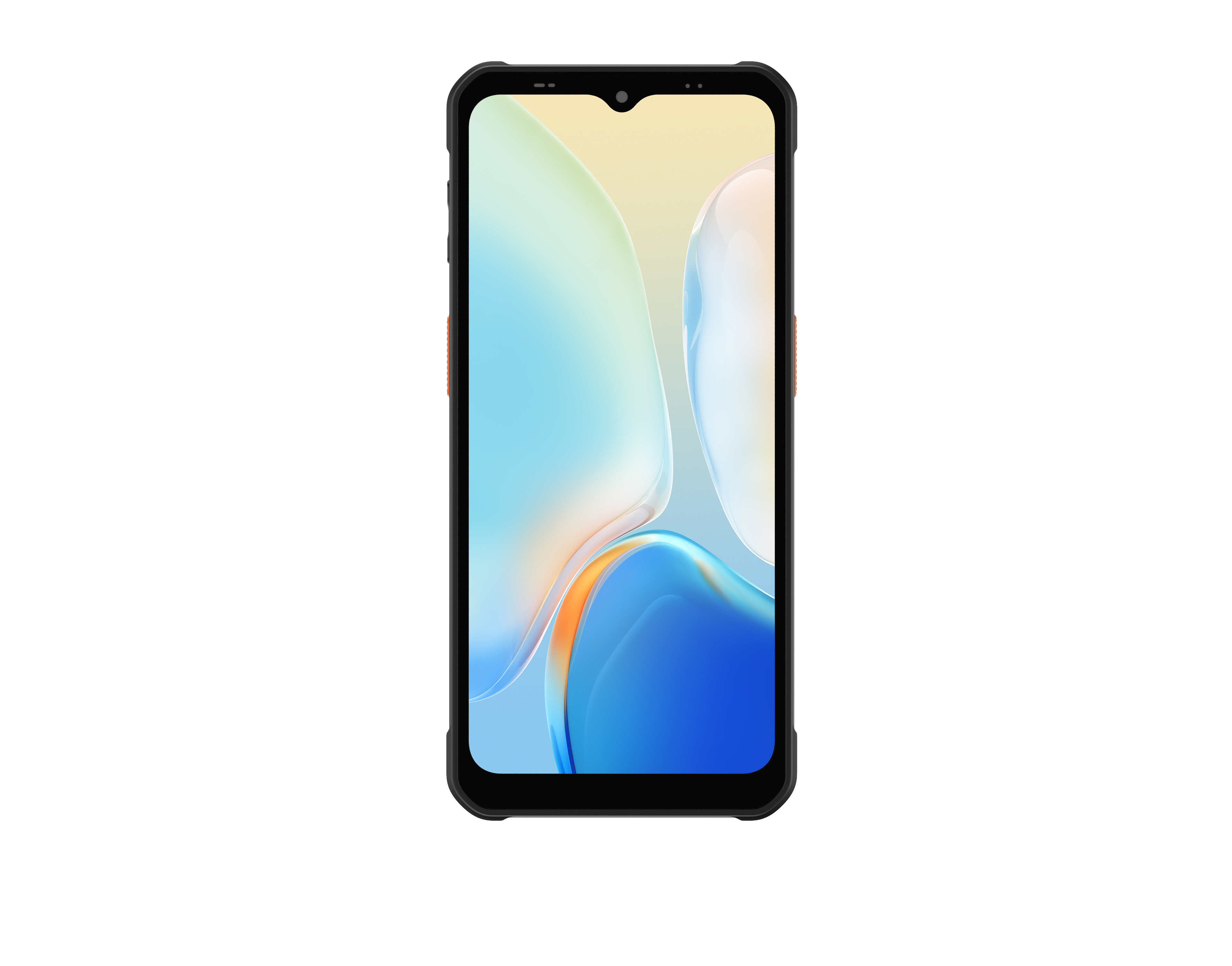 DT630
New
DT630
New
 DT66
New
DT66
New
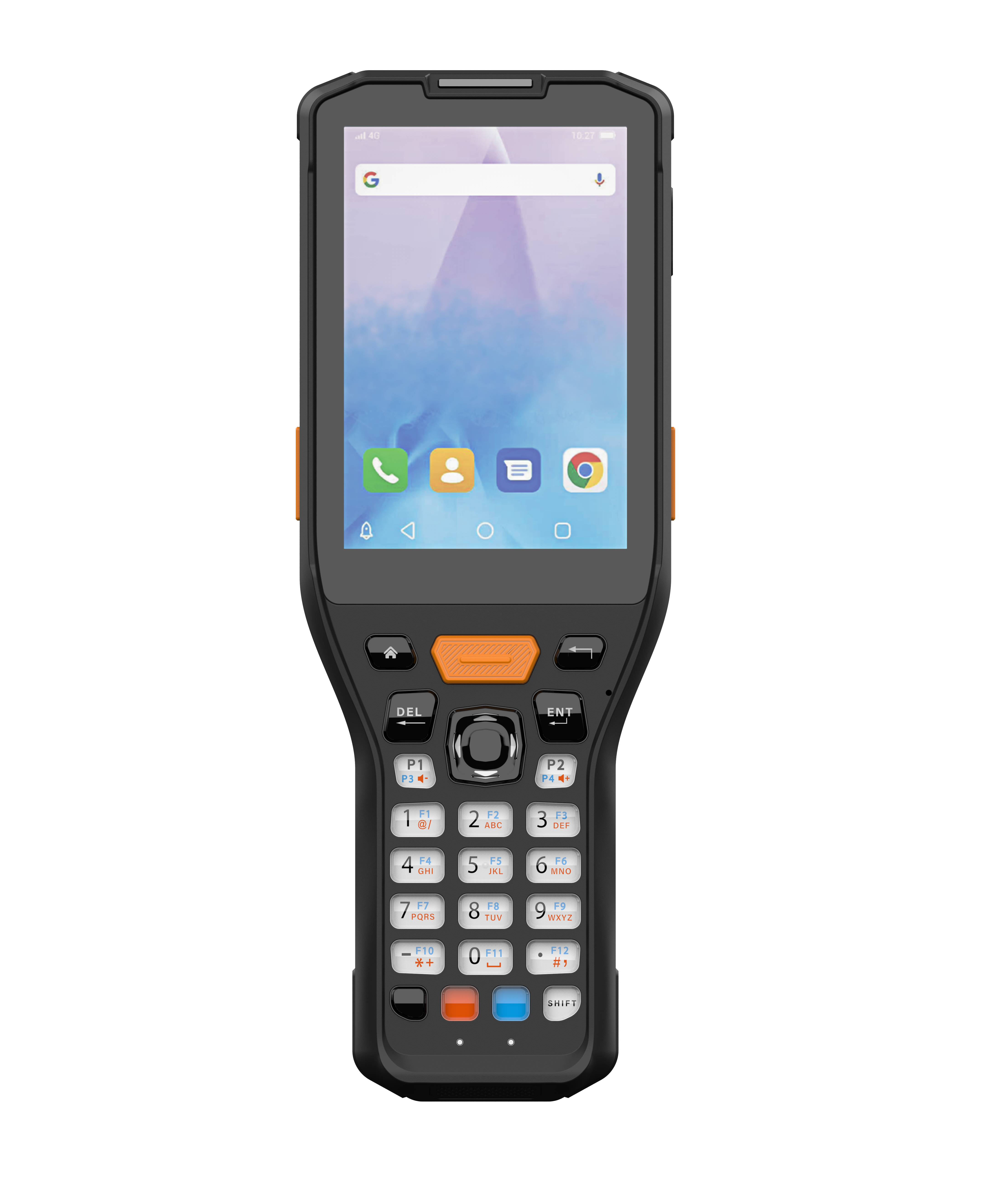 RT30
New
RT30
New
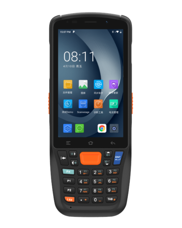
 DT50
DT50
 CT48
CT48
 CT58S
CT58S
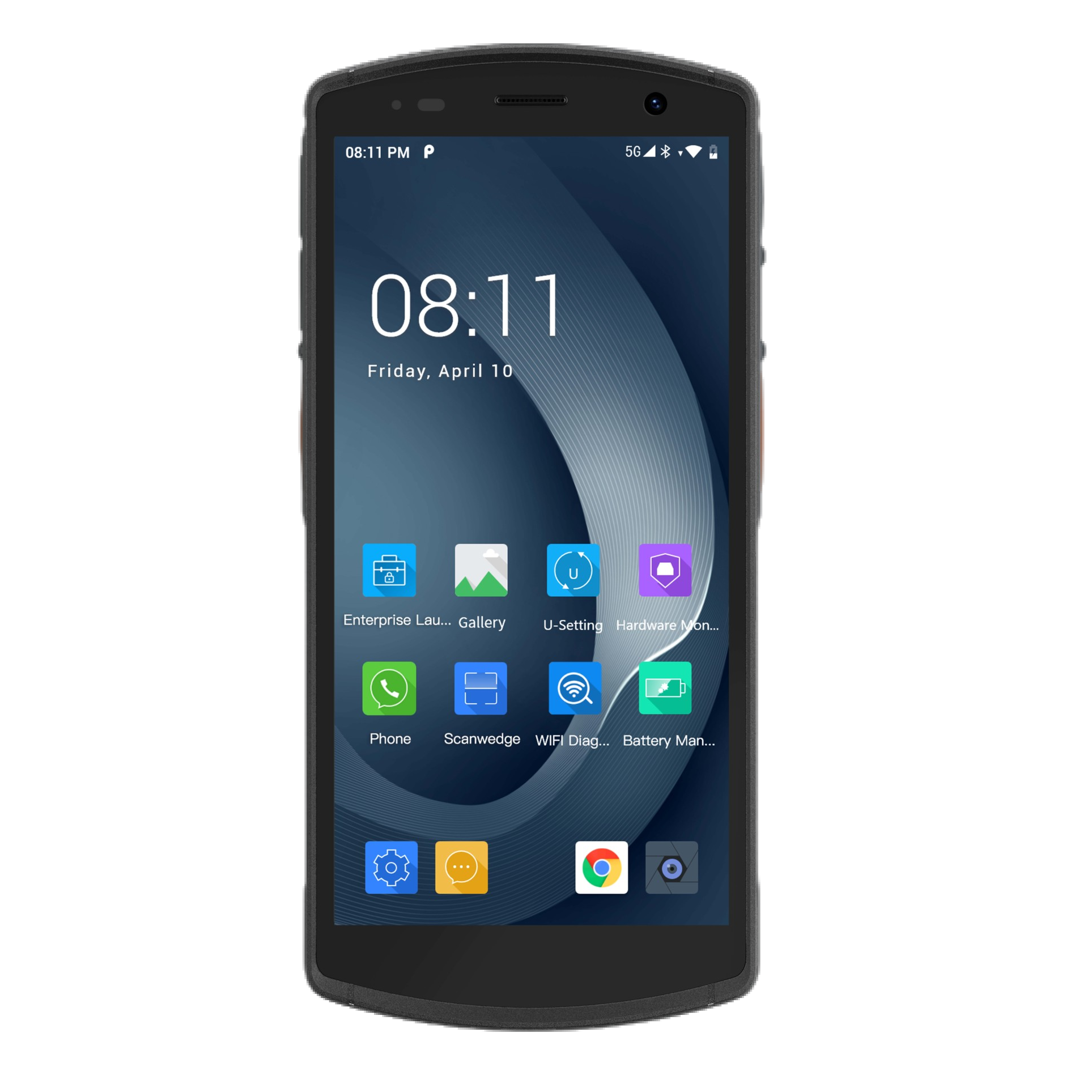
 DT50 5G
 DT40
DT40
 RT40S
RT40S
Wearable Computer
 U2S
New
U2S
New
 R7 Series
-
RFID Devices
Handheld RFID Reader
 DT610
New
DT610
New
 DT50P Lite
New
DT50P Lite
New
 DT50(P)
 DT50(D)
Fixed RFID Reader
 FR7000 Series
New
FR7000 Series
New
 FR2000
New
FR2000
New
 FR1000
RFID Sled
 RFG91
New
RFG91
New RFID Printer
 D81R Series
New
D81R Series
New -
Healthcare Devices
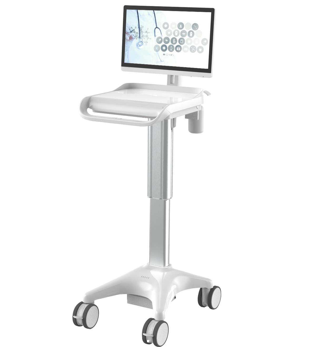
 T3 Series Medical Nursing Mobile Stations
New
T3 Series Medical Nursing Mobile Stations
New
 T3 Series Medical Telemedicine Mobile Stations
New
T3 Series Medical Telemedicine Mobile Stations
New
 T3 Series Medical Consultation Mobile Stations
New
T3 Series Medical Consultation Mobile Stations
New
 T3 Series Medical Grade Desktop Computer (AIO)
New
T3 Series Medical Grade Desktop Computer (AIO)
New
 DT505G (Healthcare)
 DT50H
DT50H
 P8100H
Rugged Tablets
P8100H
Rugged Tablets
 P8100 4G
New
P8100 4G
New
 P8100P Series
-
Barcode Scanners
 K180
New
K180
New
 K200
New
K200
New
 K220
Printers
K220
Printers
Mobile Printers
 K388 Pro
New
K388 Pro
New
 K329
K329
 K419
K419
-
- Software Tools
-
Support
 Resources
 - Partners
-
About Urovo
 Pioneer of mobile computers
and payment terminals manufacturer